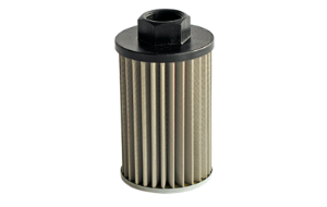
Suction filters clean the oil from the tank in many different applications before it is sucked into the working circuit by the pump and thus enters the system.
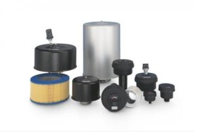
Air & Desiccant Breathers
Air breathers protect the system from outside contamination, while desiccant breathers prevent moist air from entering the hydraulic system.
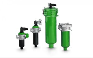
Return Line Filters
All impurities generated in the system and flushed from the hydraulic system are collected by the return line filter, thereby preventing the development of a cycle of contamination through the tank and pump.
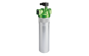
Low Pressure Filters
In the low pressure range up to 25/60 bar, Filtration Group Industrial offers low pressure filters as in-line filters, flanged filters and filters in intermediate plate design.
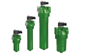
Medium/High Pressure Filters
We cover a wide range of applications. A robust housing withstands heavy operating pressure and the streamlined design ensures maximum performance.
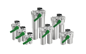
Duplex Filters
Duplex filters allow a filter change during live operation and are thus suitable for use in motors and drives that have to reliably run continuously. Thanks to the compact design, duplex filters require little space and have a low flow resistance.
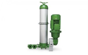
Oil care
Whether oil separators or oil filter modules, we offer a wide range of products for oil care.
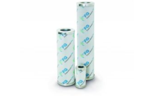
Filter Elements
Always specially matched to the required cleanliness class, the pressure conditions and the nature of the medium, our filter elements guarantee efficient operation.
Unit 4/191 Allambie Road, Frenchs Forest, NSW 2086, Australia